File list
Jump to navigation
Jump to search
This special page shows all uploaded files.
| Date | Name | Thumbnail | Size | User | Description | Versions |
|---|---|---|---|---|---|---|
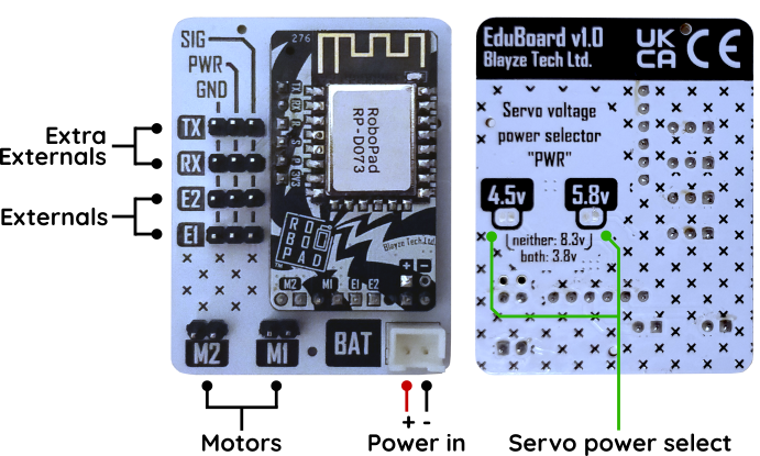
| 01:36, 24 March 2026 | RoboPad + EduBoard pinout.png (file) |  |
338 KB | Blayze | 1 | |
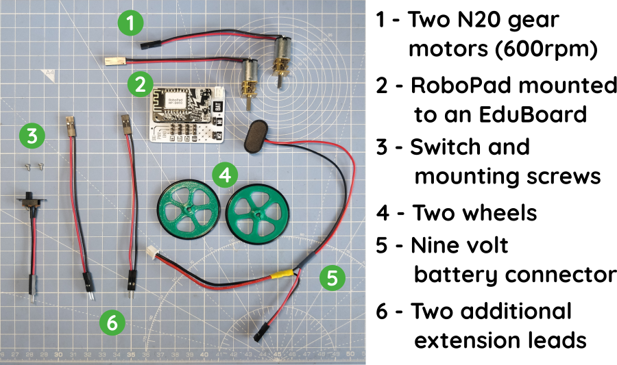
| 01:28, 23 March 2026 | SMRRF 2026 Kit Components.png (file) |  |
527 KB | Blayze | 1 | |
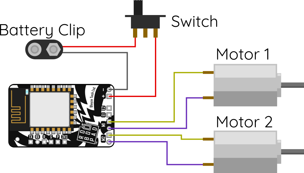
| 19:08, 9 December 2024 | Robopad-kit-wiring-diagram.png (file) |  |
64 KB | Blayze | 1 | |
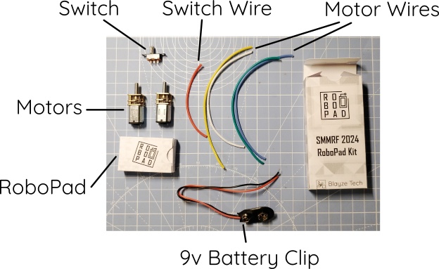
| 19:07, 9 December 2024 | RoboPad-kit-contents.png (file) |  |
202 KB | Blayze | 1 | |
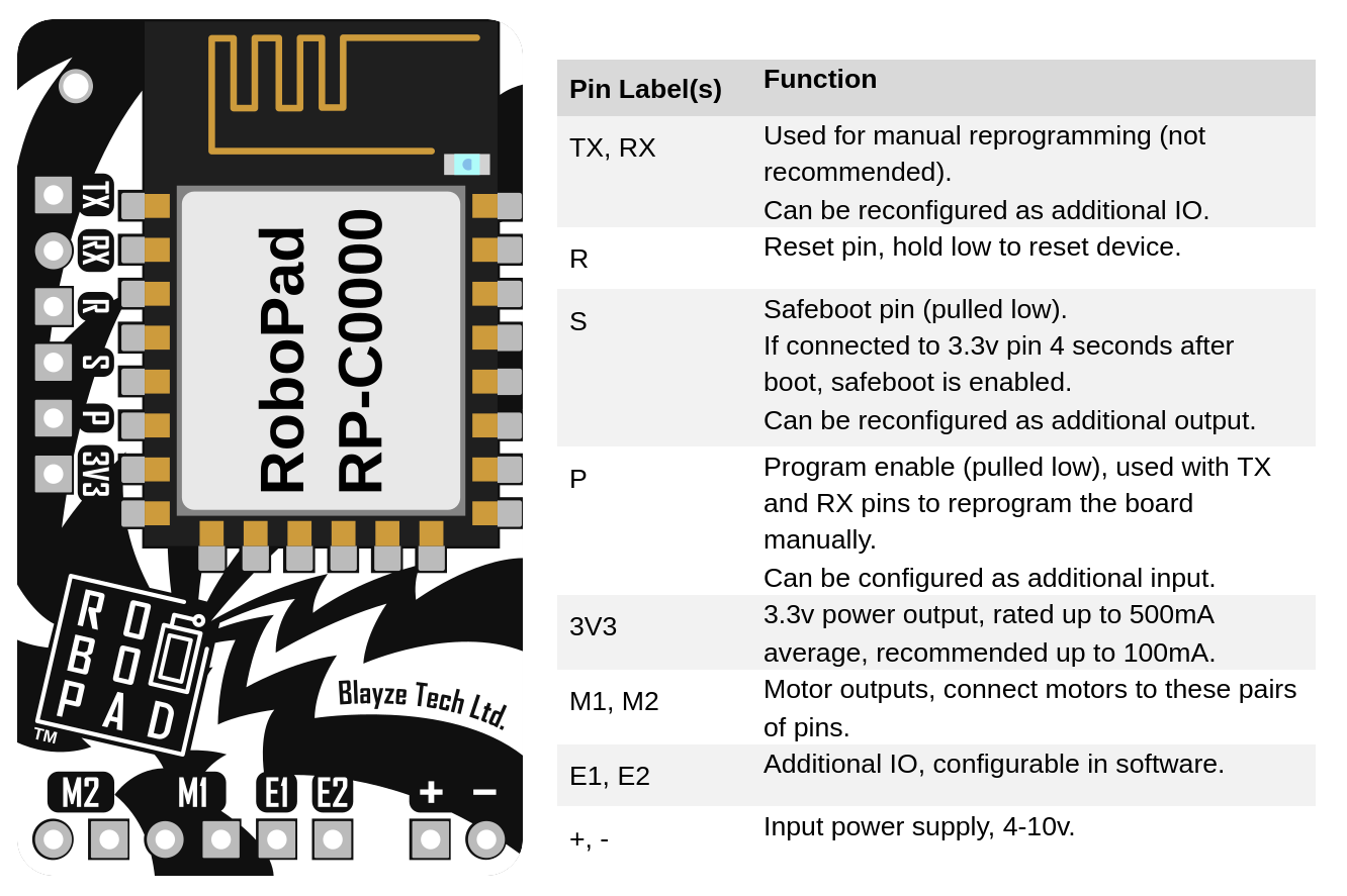
| 23:35, 5 October 2024 | RoboPad 1.3 Pinout.png (file) |  |
207 KB | Blayze | Adds maximum motor output current to image. | 2 |
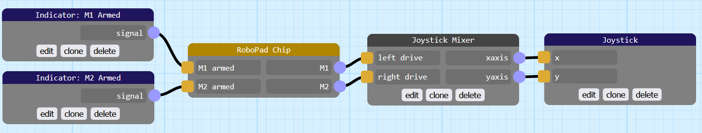
| 02:40, 21 August 2024 | Joystick-drive-with-indicators.PNG (file) | 33 KB | Blayze | An example nodegraph that uses a joystick node. | 1 | |
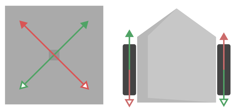
| 02:30, 21 August 2024 | Good-joystick-diagram.png (file) |  |
15 KB | Blayze | An example of the control scheme of a properly mixed joystick. | 1 |
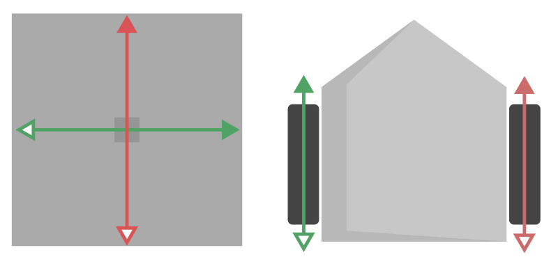
| 02:29, 21 August 2024 | Bad-joystick-config-diagram.PNG (file) |  |
13 KB | Blayze | An example of what a bad joystick configuration results in, robot-movement wise. | 1 |
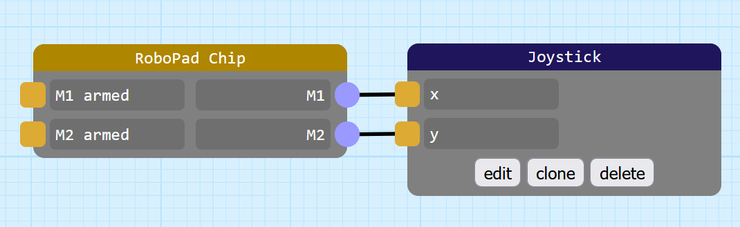
| 02:10, 21 August 2024 | Bad-joystick-config.PNG (file) |  |
27 KB | Blayze | An example of a misconnected joystick node. | 1 |
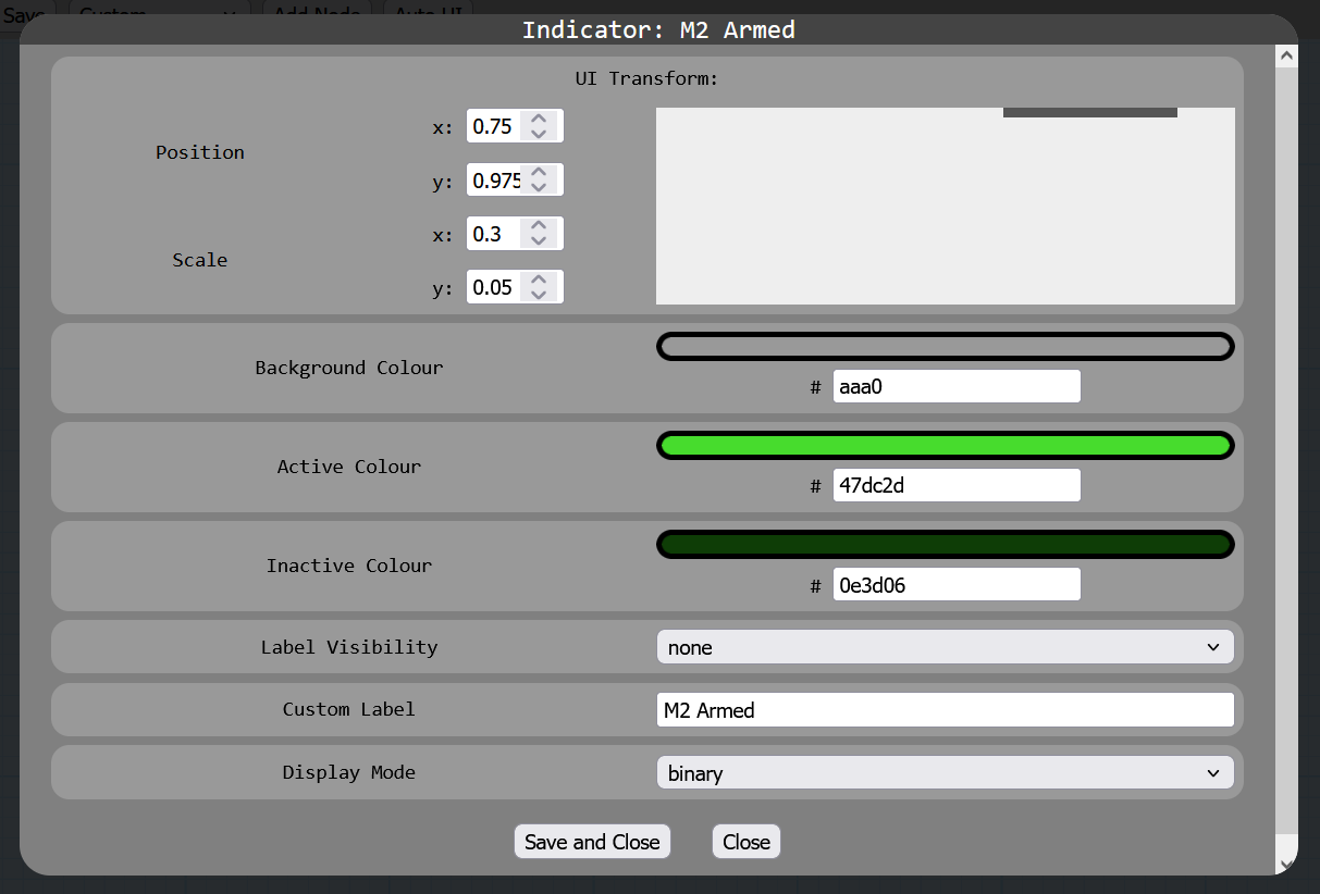
| 01:45, 21 August 2024 | Indicator-tankdrive-right-indicator.PNG (file) |  |
51 KB | Blayze | The right indicator config for a basic tankdrive nodegraph with indicators. | 1 |
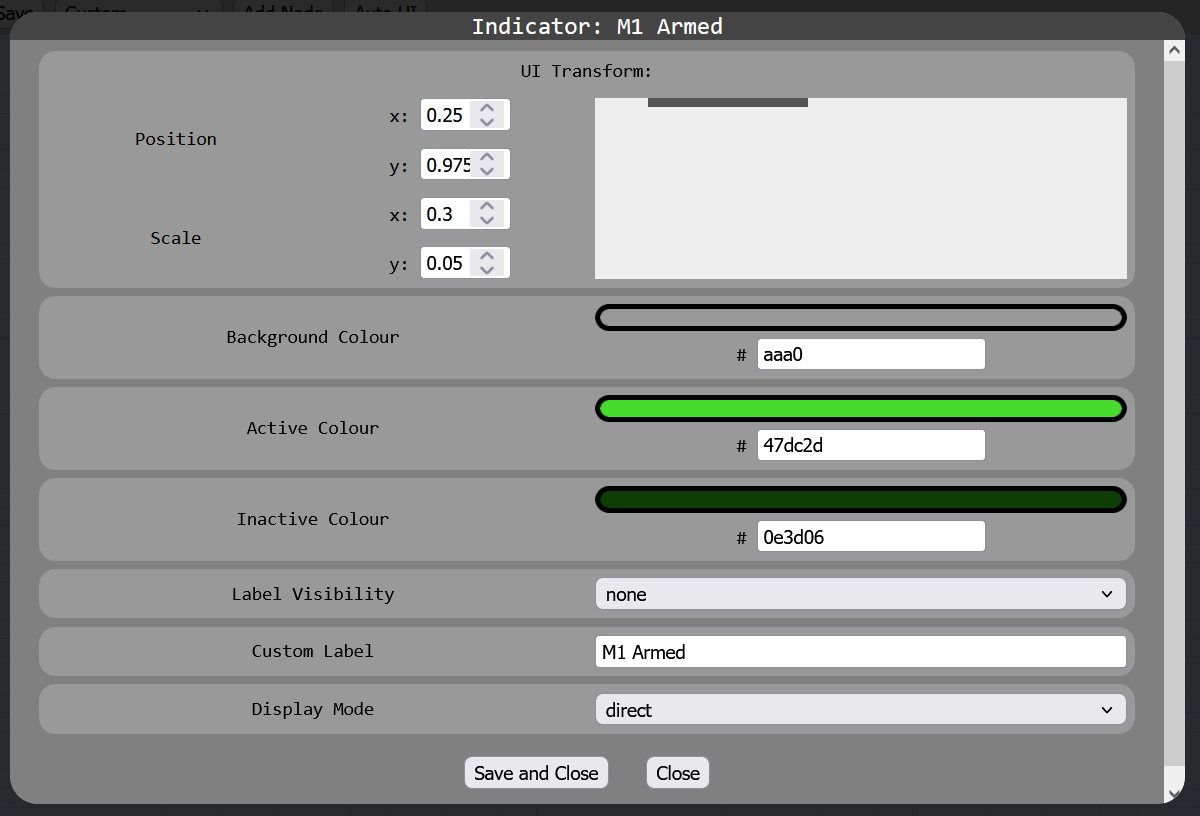
| 01:45, 21 August 2024 | Indicator-tankdrive-left-indicator.PNG (file) |  |
50 KB | Blayze | The left indicator config for a basic tankdrive nodegraph with indicators. | 1 |
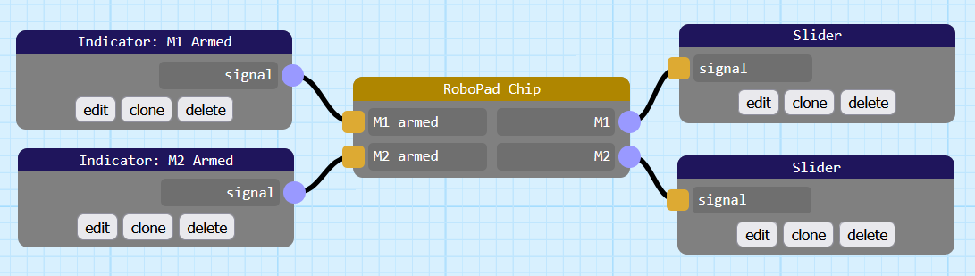
| 01:44, 21 August 2024 | Indicator Tankdrive Nodegraph.png (file) |  |
31 KB | Blayze | A basic tankdrive nodegraph with indicators. | 1 |
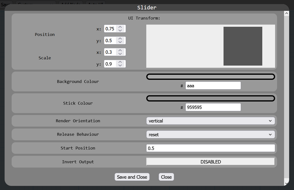
| 01:34, 21 August 2024 | Basic Tankdrive Right Slider.png (file) |  |
47 KB | Blayze | The basic tankdrive right slider configuration. | 1 |
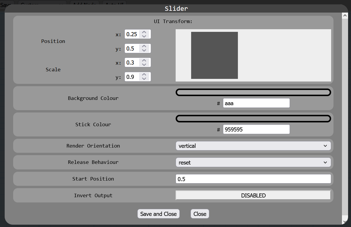
| 01:34, 21 August 2024 | Basic Tankdrive Left Slider.png (file) |  |
46 KB | Blayze | The configuration of the left slider of a basic tankdrive configuration. | 1 |
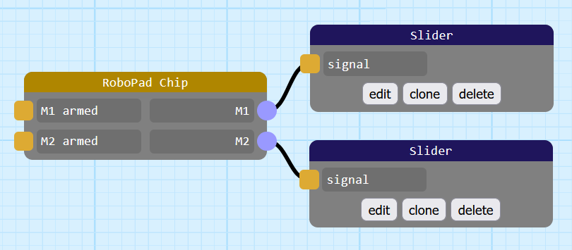
| 01:33, 21 August 2024 | Basic Tankdrive.png (file) |  |
24 KB | Blayze | The most basic tankdrive configuration, with no indicators. | 1 |
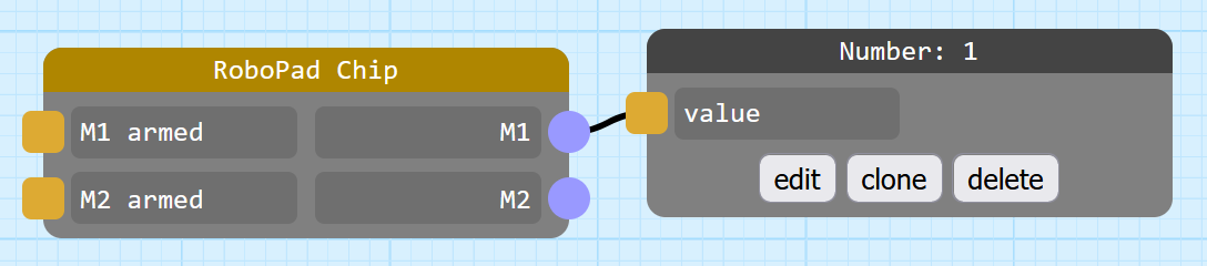
| 01:26, 21 August 2024 | Non-Armable Configuration.png (file) | 24 KB | Blayze | 1 | ||
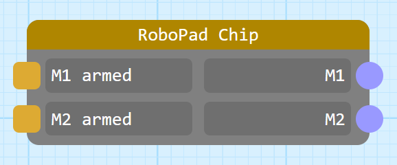
| 01:10, 21 August 2024 | Chip Node with Default IO.png (file) |  |
13 KB | Blayze | 1 | |
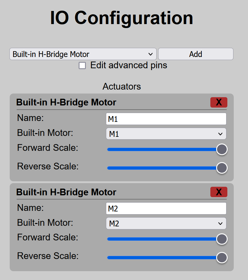
| 01:05, 21 August 2024 | Default IO Units.png (file) |  |
82 KB | Blayze | 1 | |
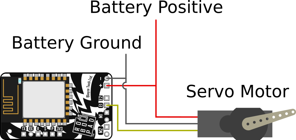
| 01:14, 10 July 2024 | Servo Wiring Diagram.png (file) |  |
64 KB | Blayze | A basic example of a servo motor connected to a RoboPad. | 1 |
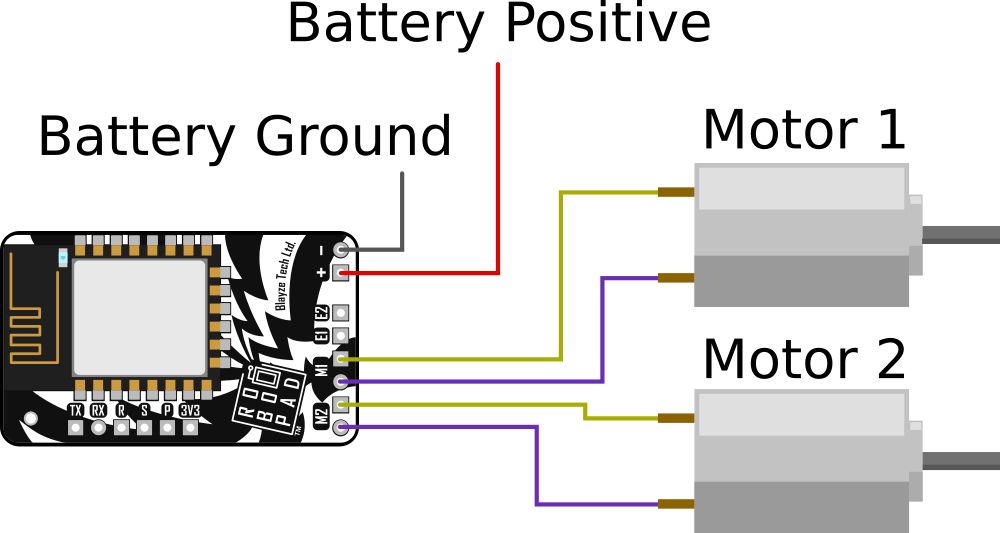
| 00:56, 10 July 2024 | Basic 2-Motor wiring diagram.png (file) |  |
61 KB | Blayze | 1 | |
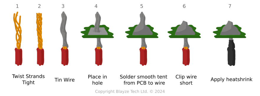
| 21:57, 10 June 2024 | Soldering Tips.png (file) |  |
64 KB | Blayze | 1 | |
| 16:54, 14 May 2024 | Joystick-mixer-example-controller.gif (file) |  |
245 KB | Blayze | Half-sized image, hopefully allowing for it to play in-thumbnail. | 2 |
| 14:31, 9 May 2024 | Address-connection-poster.png (file) |  |
23 KB | Blayze | 1 | |
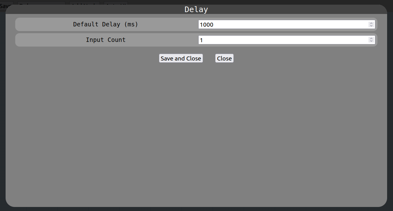
| 23:33, 7 March 2023 | Delay-settings.png (file) |  |
25 KB | Blayze | Now reflects multi-io delay node. | 2 |
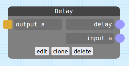
| 23:32, 7 March 2023 | Delay-node.png (file) |  |
13 KB | Blayze | Now reflects multi-io delay node. | 2 |
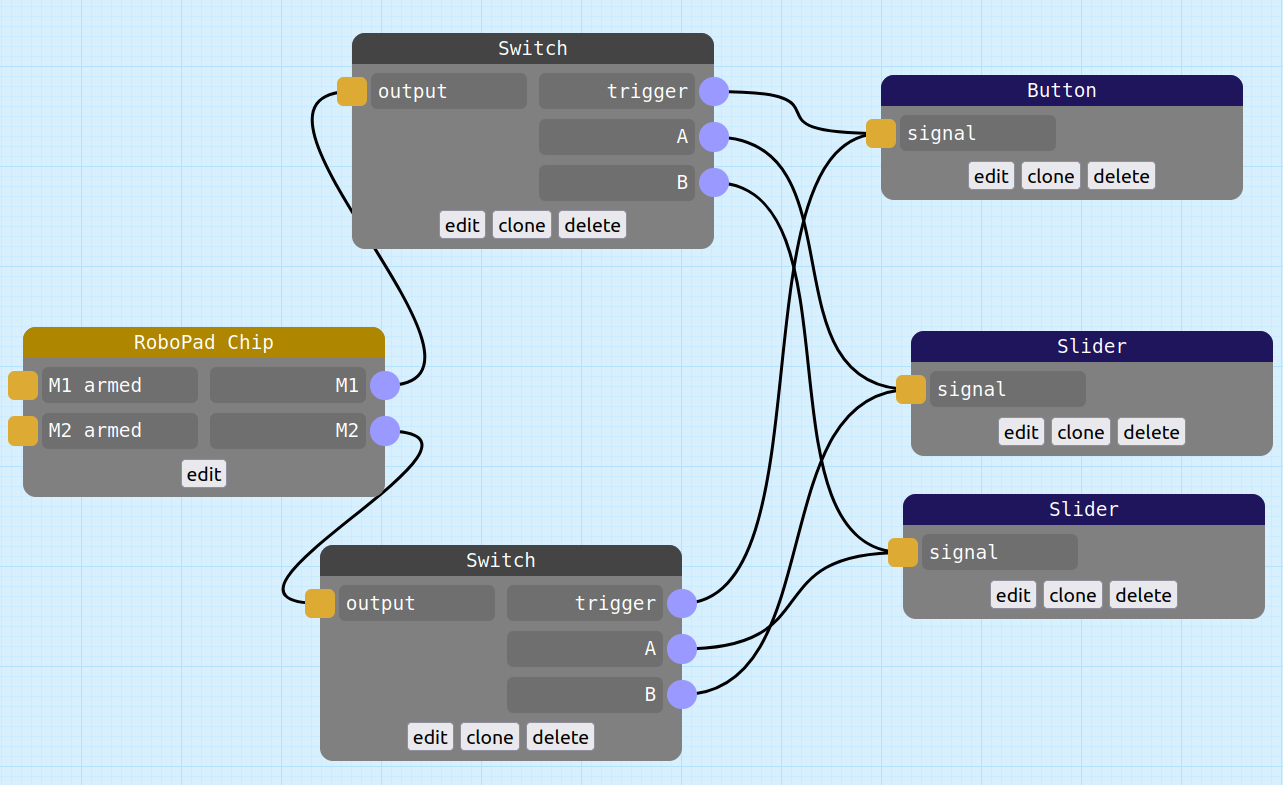
| 22:51, 7 March 2023 | Switch-node-example-nodegraph-2.png (file) |  |
109 KB | Blayze | A simple nodegraph example that shows (particularly when in conjunction with the Switch-node-example-nodegraph.png File) that you can achieve a simple drive inversion circuit without an inverter node, just by switching the inputs on one half of a Switch Node pair. | 1 |
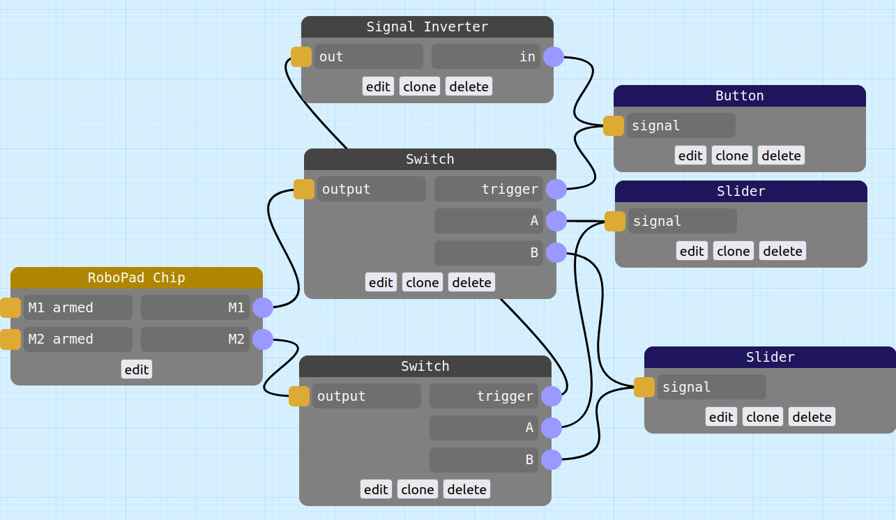
| 22:20, 7 March 2023 | Switch-node-example-nodegraph.png (file) |  |
106 KB | Blayze | An example nodegraph that uses a switch node to invert the left/right steering sliders in a tank-drive controller based on a button press. | 1 |
| 03:27, 6 March 2023 | Joystick-mixer-demo-nodegraph.png (file) |  |
360 KB | Blayze | The nodegraph used to generate the joystick mixer node demo controller recording. | 1 |