IO Config Editor
NOTICE: This page consists of information on a feature currently in Beta. Information is liable to change or be incomplete.
The Input/Output (IO) Configuration Editor page is the page where you can edit the physical IO configuration of the RoboPad board by configuring IO Units. You can, for instance, set one of the external pins to output a digital electronic signal, which can be controlled via the nodegraph. It is accessible via the Management Page.

Each IO Unit has a number of settings and will add it's own input and output ports to the Chip Node in the nodegraph. Importantly, for actuators, you are able to specify safe values - these are the values that the IO Unit will default to when the RoboPad looses connection to your phone or you are on any screen other than the controller screen (it's emergency stop state). It is very important that you understand how your safe values and IO Units in general interact with the physical circuitry you have added to your RoboPad - for instance, if you are adding an additional motor to your robot using a Generic PWM IO Unit, you will most likely want to ensure that it's safe value is set to 0 so that it will turn off in an emergency situation. Some IO Units do not have safe value settings (such as HBridge motors and unidirectional brushless motors) as all of these configurations are configured to turn off by default.
Changing the physical configuration of the RoboPad and the behaviour of it's pins using the IO Configuration Editor should be considered an advanced topic - ensure that you have read and fully understand everything on this wiki page and everything you are doing before attempting to change these settings.
Emergency Stop Behaviour When Changing IO Unit Configuration
It is also important to understand that IO Unit safe values remain configured on the pins they are set to, even when removed (using the red "x") until either another IO Unit is configured to use that pin or the device is reset. This has been done because it is not recommended, expected or suggested that a user would change the physical configuration of their RoboPad circuit without first powering it down. Therefore, the firmware assumes that the safest thing to do is retain the last set safe value for any given pin until it is told otherwise (or the device is power cycled, at which point unconfigured pins remain at a high-impedance state).
"Advanced Pins"
Some Pins - namely all pins that are not External 1 and External 2 (marked E1 and E2 respectively on the board) are considered Advanced Pins. This is because they may behave in a way outside of expected behaviour. For instance, many of these pins will output arbitrary signals within the first 500 milliseconds of RoboPad boot and as such should not be used for actuators that may cause harm if they were to unexpectedly move. Others (particularly the "Internal" pins) are already connected to some internal electronics on the RoboPad, such as the built-in HBridge that drives the default M1 and M2 outputs. In order to use these pins, you would have to remove the HBridge from the device (which is not advised and will void the product's guarantee).
Pins

Much like an Arduino, pins are capable of driving a small current (~12mA per pin) at 3.3v to external circuitry, or can sink a small current (~20mA). Below is a list of the different pin names and how they might be used.

| Pin Name | ID on Board | Information |
|---|---|---|
| External 1 | E1 | Non-advanced pin. |
| External 2 | E2 | Non-advanced pin. |
| TX | T | The "Transmit" pin when manually reprogramming the RoboPad.
Subject to pseudo-random signal state for the first 500ms after RoboPad boot. |
| RX | R | The "Recieve" pin when manually reprogramming the RoboPad.
Subject to pseudo-random signal state for the first 500ms after RoboPad boot. |
| Safeboot | SB | Pulled low through an on-board 10kΩ resistor, and meant to be connected to the 3.3v pin (pulling it high) at the 4 seconds after boot point to enable safeboot.
Subject to pseudo-random signal state for the first 500ms after RoboPad boot. |
| Program Enable | PE | Used along with the TX and RX pins to manually reprogram the RoboPad.
Subject to pseudo-random signal state for the first 500ms after RoboPad boot. |
| Unset | When "Unset" is available, the pin may optionally be non-configured. Choosing this option means no pin is used for the particular option. | |
| Drive Enable | Internal | An internal pin used to enable or disable the built-in HBridge chip.
Subject to pseudo-random signal state for the first 500ms after RoboPad boot. |
| Drive Pin 1
Forward |
Internal | An internal pin attached to the built-in HBridge chip.
Subject to pseudo-random signal state for the first 500ms after RoboPad boot. |
| Drive Pin 1
Backward |
Internal | An internal pin attached to the built-in HBridge chip.
Subject to pseudo-random signal state for the first 500ms after RoboPad boot. |
| Drive Pin 2
Forward |
Internal | An internal pin attached to the built-in HBridge chip.
Subject to pseudo-random signal state for the first 500ms after RoboPad boot. |
| Drive Pin 2
Backward |
Internal | An internal pin attached to the built-in HBridge chip.
Subject to pseudo-random signal state for the first 500ms after RoboPad boot. |
IO Units
A variety of IO Units can be added that are suitable for a number of uses, all are listed here.
Actuators
All actuators add input ports to the Chip Node, allowing signals to be passed from the Node Graph to each actuator. On top of this, each actuator will create an output port on the Chip Node, usually labelled ending with "Armed" - this is an indicator of whether or not the actuator is armed. The signal to any specific actuator must pass through that actuator's configured safe value for it to be considered to be armed - then and only then will the actuator start to process new control signals. As an example, an servo attached using the "PWM Output" with a safety value set to 50% would require a near-50% signal to be sent to it's input before you will be able to see any change in the pin's output.
All actuators output 3.3 volts along their output pins. Make sure that any connected peripherals such as ESCs or H-Bridges operate with 3.3 volt logic.
H-Bridge Motor

A H-Bridge is a simple, common circuit that can control the polarity of electricity to an attached electrical component - commonly a motor. In practice this means that a typical brushed DC motor's direction and speed can be controlled from one using two control signals. While you can make one yourself using transistors (that site also has a useful example using switches which might make the concept easier to understand too), they often come in integrated circuit (IC) form factors, such as the Texas Instruments L293D, which packs two H-bridges and comes bundled with some additional features.
Using this IO Unit, the RoboPad will send drive signals suitable for use with a H-bridge through the specified pins (PinA and PinB). It's emergency stop state is to stop all signals and power down associated pins. The nodegraph is expected to supply a value between 0 and 1 to this IO Unit's input port, where 0 is maximum reverse rotation, 0.5 is stationary and 1 is maximum forward rotation. This IO Unit creates an output port (labeled "<name> armed") on the Chip Node that signals high (1) when a control signal has been passed to it that would place it into it's safe state.
- Name: The name of this HBridge motor, basically only changes the name of the motor input port on the Chip Node.
- Pin A: One of the two directional signals needed by H-Bridge chips.
- Pin B: One of the two directional signals needed by H-Bridge chips, signalling the opposite direction from that signalled in Pin A.
- Enable Pin: If set to a value other than "Unset", a high signal will be transmitted whenever the H-Bridge is in use; to be connected to a H-Bridge chip's "enable" pin(s).
- Forward Scale: Scales the forward signal (over 50%) before it is transmitted to the motor signal pins - if your motor drives forward faster than backwards, then you can lower this value.
- Reverse Scale: Scales the backward signal (below 50%) before it is transmitted to the motor signal pins - if your motor drives backwards faster than forwards, then you can lower this value.
Built-in H-Bridge Motor

The "Built-in H-Bridge Motor" IO unit is a specialised version of the "H-Bridge Motor" above, specifically designed to work only with the two built-in H-Bridges on the RoboPad, allowing you to select motors to be attached to the M1 and M2 pin pairs on the board. By default, two of these are configured, one for M1 and one for M2. When in the emergency stop state, these IO Units attempt to send a stop signal to any attached motors, not powering any associated pins. Just as in the "H-Bridge Motor" IO Unit, the nodegraph is expected to supply a value between 0 and 1 to this IO Unit's input port, where 0 is maximum reverse rotation, 0.5 is stationary and 1 is maximum forward rotation. This IO Unit creates an output port (labeled "<name> armed") on the Chip Node that signals high (1) when a control signal has been passed to it that would place it into it's safe state.
- Name: The name of this HBridge motor, basically only changes the name of the motor input port on the Chip Node.
- Built-in Motor: Which of the two built-in motor pins this H-Bridge Motor IO Unit references - M1 connects to the M1 pins, M2 to the M2 pins.
- Forward Scale: Scales the forward signal (over 50%) before it is transmitted to the motor signal pins - if your motor drives forward faster than backwards, then you can lower this value.
- Backward Scale: Scales the backward signal (below 50%) before it is transmitted to the motor signal pins - if your motor drives backwards faster than forwards, then you can lower this value.
Unidirectional Brushless Motor

A brushless motor is a type of motor that uses many (usually three) electromagnetic circuits, pulsed in a specific sequence to generate a moving magnetic field - this field then "pulls" the motor's magnetised rotor with it, allowing for rotation without direct electrical contact (as is found in brushed motors, where metal brushes must transfer power directly to the rotor), resulting in motors that are less prone to wear and generally operate more smoothly and efficiently. The downside of this is that they require electronic speed controllers (ESCs) to be driven, which are circuits containing microprocessors that power the motor's coils in the correct sequential pattern. These ESCs take in a control signal, and will often require an arming sequence before they start to energise the motor's coils.
The "Unidirectional Brushless Motor" IO Unit allows the RoboPad to send drive signals (much as a traditional RC radio receiver would) suitable for reception by an ESC that can accept a PWM control signal, and will automatically send thvcbe configured arming sequence beforehand in order to initialise the ESC ready for motor control. Note that this only configures one pin as a control signal pin, and as such is designed to work with unidirectional brushless motor ESCs, i.e. ESCs that allow a single motor to be driven in a single direction at varying speeds. An incoming nodegraph signal of 0 results in the minimum microseconds signal being sent to the ESC, while an incoming nodegraph signal of 1 results in the maximum microseconds signal being sent to the ESC. This IO Unit creates an output port (labeled "<name> armed") on the Chip Node that signals high (1) when a control signal has been passed to it that would place it into it's safe state.
- Name: The name of this brushless motor, basically only changes the name of the motor input port on the Chip Node.
- Pin: Which pin will generate the ESC control signal.
- Minimum Microseconds [Advanced]: The minimum value the PWM control signal generated has (i.e. what it has when a 0/low signal is sent to the IO Unit via the nodegraph). Only change this if you know what you are doing!
- Maximum Microseconds [Advanced]: The maximum value the PWM control signal generated has (i.e. what it has when a 1/high signal is sent to the IO Unit via the nodegraph). Only change this if you know what you are doing!
- Arm Sequence: The sequence of signals that must be sent to the ESC to arm it. Refer to your ESC's manual to understand it's arming sequence and select the appropriate option here. If none match, drop us a line and tell us.
Note: Many ESCs will emit a "standby" noise if you have them armed but not in use for a prolonged time. This is usually expressed as the motor spinning small amounts to beep every few seconds.
Servo Motor

A servo motor is a motor/control board combination integrated circuit that takes a control signal and actuates to a position within its range of movement that aligns with the received signal.
The "Servo Motor" IO Unit allows the RoboPad to send PWM drive signals that a servo motor can interpret. While the control signal provided by the RoboPad is at 3.3v and as such should work fine under most common servos, they will require their own power supply - some servos accept a range of input voltages and will be suitable to power directly from your robot's power source (such as a battery), but others will require power circuitry to ensure that you are providing them a safe and expected voltage. In a similar vein, make sure that you can provide the appropriate voltage and currant to your servo motor. The 5v output pin of the RoboPad is only rated up to 500mA (and it already powers the built-in Dual H-Bridge), and many servos will require either a higher voltage or draw a higher current, which could damage the board. Always refer to your motor's manual and/or technical information and verify that it will work with the rest of your electrical circuit. This IO Unit creates an output port (labeled "<name> armed") on the Chip Node that signals high (1) when a control signal has been passed to it that would place it into it's safe state.
- Name: The name of this servo motor, basically only changes the name of the motor input port on the Chip Node.
- Pin: Which pin will generate the PWM control signal.
- Minimum Microseconds: The minimum value the PWM control signal generated has (i.e. what it has when a 0/low signal is sent to the IO Unit via the nodegraph). Only change this if you know what you are doing!
- Maximum Microseconds: The maximum value the PWM control signal generated has (i.e. what it has when a 1/high signal is sent to the IO Unit via the nodegraph). Only change this if you know what you are doing!
- Disconnect Behaviour: What this IO Unit should do in the emergency stop state. By default this is "Stay in place" meaning that the control signal will remain at what it last sent - this makes sense for most servo-based actuators as in an emergency stop state, you would not want the servo moving. However, in some cases you may want the servo to move to a pre-defined position. In that case this can be set to "Return to disconnect %" which will set the servo control signal to Disconnect Percent (defined below) in the emergency stop state.
- Disconnect Percent: The percent, relative from the minimum microseconds value (0%) to the maximum microseconds value (100%) to return to when entering the emergency stop state if Disconnect Behaviour is set to "Return to disconnect %".
Digital Output

The simplest IO Unit actuator, the "Digital Out" IO Unit sets a physical pin as a binary digital output, similar to those you might find on an arduino. As a control signal comes into the IO Unit via the nodegraph, if the value is over 0.5 then a logical high (at 3.3 volts) is sent out of the selected pin, if the value is below 0.5 then a logical low (at 0 volts) is sent out of the selected pin. When you are driving external devices (such as LEDs, motors, etc), remember that the pins can only drive a small current (chip specifications recommend ~12mA source, ~20mA sink) so you may want to use a transistor to drive heavier loads. This IO Unit creates an output port (labeled "<name> armed") on the Chip Node that signals high (1) when a control signal has been passed to it that would place it into it's safe state.
- Name: The name of this digital output, basically only changes the name of the input port on the Chip Node.
- Pin: Which pin will generate the digital signal.
- Safety Value: What value to output when in the emergency stop state if the Stop Behaviour is configured as "Return to safe".
- Stop Behaviour: What this IO Unit should do when the RoboPad goes into the emergency stop state. By default "Return to safe", meaning that it will transmit the value set in Safety Value.
PWM Output

The "PWM Output" IO Unit sets a physical pin as a PWM pseudo-analog output, similar to those you can configure on an arduino. As the signal (between 0 and 1) comes into the IO Unit via the nodegraph, the value is then ouput as a PWM signal from the RoboPad "between" 0 and 3.3 volts. When you are driving external devices (such as LEDs, motors, etc), remember that the pins can only drive a small current (chip specifications recommend ~12mA source, ~20mA sink) so you may want to use a transistor to drive heavier loads. This IO Unit creates an output port (labeled "<name> armed") on the Chip Node that signals high (1) when a control signal has been passed to it that would place it into it's safe state.
- Name: The name of this PWM output, basically only changes the name of the input port on the Chip Node.
- Pin: Which pin will generate the PWM control signal.
- Safety Value: The percent, relative from the minimum microseconds value (0%) to the maximum microseconds value (100%) to return to when entering the emergency stop state if Stop Behaviour is set to "Return to safe".
- Stop Behaviour: What value to output when in the emergency stop state if the Stop Behaviour is configured as "Return to safe".
Physically Attaching Hardware
Hardware such as motors typically connects to one of the M1 or M2 output pairs or the E1 and E2 output pins (or others if in advanced mode, as laid out in the "Pins" section above). While M1 and M2 can drive motors directly via a passthrough to the RoboPad's supply voltage, motors that require their own voltage supply such as servos or brushless motors will require a connection directly to their own power supply. Typically this is the same power source as that used to power the RoboPad, however it could also be a battery elimination circuit (BEC) or any other voltage-appropriate power source. The images below show some example wiring diagrams (use the left and right buttons to change between images):
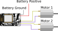
The most basic RoboPad circuit configuration, consisting of two drive motors connected to the M1 and M2 pin pairs.
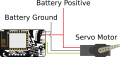
A servo motor with it's control signal connected to the E1 pin, while it's power supply is connected to the same battery power supply powering the RoboPad.

