Example: Simple Tank-Drive Robot: Difference between revisions
No edit summary |
(Adds instructions on how to download the nodegraph.) |
||
| (7 intermediate revisions by the same user not shown) | |||
| Line 1: | Line 1: | ||
'''''<u>NOTICE: This page consists of information (the IO Config editor) on a feature currently in [[Beta]]. Information is liable to change or be incomplete. However, a similar nodegraph is constructable for version 2.3 or lower builds of RoboPad.</u>''''' | |||
A tank-drive robot is the most simple type of robot that you can make with a RoboPad. It is the default configuration that the roboPad is set up for and allows for driving two motors using two sliding sticks ([[Slider Node|Sliders]]) - one to control power to the left motor and one to control power to the right motor. This page aims to give you a walk-through of building a robot like. | A tank-drive robot is the most simple type of robot that you can make with a RoboPad. It is the default configuration that the roboPad is set up for and allows for driving two motors using two sliding sticks ([[Slider Node|Sliders]]) - one to control power to the left motor and one to control power to the right motor. This page aims to give you a walk-through of building a robot like. | ||
The nodegraph from this example can be found [https://yelllowcube.sharepoint.com/:u:/s/BlayzeTechLimited/EZw9oIJKxlpOpjSIfN2ZZmgBktOBPOnqY55PVyKPJLDxrQ?e=gjRYLT here] (click the download button in the top left of the viewer to get a local copy that can be uploaded via the [[The Management Page#Node%20Graph%20Management|Nodegraph Management Page]]). | |||
The IO Configuration can be found [https://yelllowcube.sharepoint.com/:u:/s/BlayzeTechLimited/EdDMS4fiFFNBk0XiUJGwuLEB8vUZF1rG9RE07kyvFVDZIw?e=3PVTYd here]. | |||
== Hardware == | == Hardware == | ||
| Line 18: | Line 24: | ||
The two input ports - here named "M1" and "M2" (because that's the name of each motor in the IO Configuration) - drive each motor. They expect values between 0 and 1, with 0 being "full reverse" and 1 being "full forward". The two outputs - here named "M1 armed" and "M2 armed" - indicate whether the motors are [[IO Config Editor#Actuators|armed]]. The concept of actuator arming can feel a little complex, but it is important because without it the chance of accidentally driving a motor is much higher: any actuator is considered "armed" once the actuator has recieved a drive signal corresponding to it's "safe state". In the case of H-Bridge IO Units, the "safe state" is not moving, meaning that the RoboPad ''must'' recieve a value of 0.5 on each of the M1 and M2 input ports before each motor will move in any other way. Without this, it would be possible to (for example) add a signal to the M1 port that constantly fed the port with a value of "1", which would cause the robot to start driving it's M1 wheel immediately as soon as the [[The Controller|controller]] was accessed, which wouldn't be safe: | The two input ports - here named "M1" and "M2" (because that's the name of each motor in the IO Configuration) - drive each motor. They expect values between 0 and 1, with 0 being "full reverse" and 1 being "full forward". The two outputs - here named "M1 armed" and "M2 armed" - indicate whether the motors are [[IO Config Editor#Actuators|armed]]. The concept of actuator arming can feel a little complex, but it is important because without it the chance of accidentally driving a motor is much higher: any actuator is considered "armed" once the actuator has recieved a drive signal corresponding to it's "safe state". In the case of H-Bridge IO Units, the "safe state" is not moving, meaning that the RoboPad ''must'' recieve a value of 0.5 on each of the M1 and M2 input ports before each motor will move in any other way. Without this, it would be possible to (for example) add a signal to the M1 port that constantly fed the port with a value of "1", which would cause the robot to start driving it's M1 wheel immediately as soon as the [[The Controller|controller]] was accessed, which wouldn't be safe: | ||
[[File:Non-Armable Configuration.png|center|thumb|A potentially unsafe RoboPad configuration that is intended to cause the M1 motor to continually drive forward on launch. However, as M1 is a H-Bridge motor, it will never be armed as it requires the value "0.5" (no motion) to be passed to it first, so the unsafe situation is avoided.]] | [[File:Non-Armable Configuration.png|center|thumb|A potentially unsafe RoboPad configuration that is intended to cause the M1 motor to continually drive forward on launch. However, as M1 is a H-Bridge motor, it will never be armed as it requires the value "0.5" (no motion) to be passed to it first, so the unsafe situation is avoided.]] | ||
Fortunately for us, the [[Slider Node]] defaults to emitting the value 0.5, so we can simply connect two Sliders to the M1 and M2 inputs. In the images below, we've hooked them up and positioned them on the [[The Controller|Controller Stage]] so that one is on the left and one on the right: | Fortunately for us, the [[Slider Node]] defaults to emitting the value 0.5, so we can simply connect two Sliders to the M1 and M2 inputs. In the images below, we've hooked them up and positioned them on the [[The Controller|Controller Stage]] so that one is on the left and one on the right (use the left and right buttons to see additional images):<gallery mode="slideshow"> | ||
File:Basic Tankdrive.png|Two Sliders attached to the RoboPad chip node. | |||
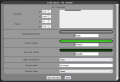
File:Basic Tankdrive Left Slider.png|The left slider configuration - it's positioned on the left of the screen, with a default value of 0.5 and "reset" behaviour. This means that as the stick is dragged up and down it will emit values between 0 and 1, driving M1 backwards and forwards, and when released it will output 0.5, stopping the motor. | |||
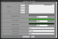
File:Basic Tankdrive Right Slider.png|The right slider configuration - it's positioned on the right of the screen, with a default value of 0.5 and "reset" behaviour. This means that as the stick is dragged up and down it will emit values between 0 and 1, driving M2 backwards and forwards, and when released it will output 0.5, stopping the motor. | |||
</gallery>However, while this is the minimum requirements to drive a robot using two sliders, it is often helpful to keep track whether your actuators are armed, which is why by default the RoboPad is bundled with a more advanced nodegraph that includes two [[Indicator Node|Indicator Nodes]] that change from dark to light green when each actuator is activated (again, use the arrows to see additional images):<gallery mode="slideshow"> | |||
File:Indicator Tankdrive Nodegraph.png|In this nodegraph, two Indicators have been added to indicate the armed status of the two drive motors. | |||
File:Indicator-tankdrive-left-indicator.PNG|The left (M1) indicator has been placed above the left slider. The label visibility has been turned off and it set to "binary" mode so that it only turns a lighter shade of green to indicate the motor is armed. | |||
File:Indicator-tankdrive-right-indicator.PNG|The right (M2) indicator has been placed above the right slider. The label visibility has been turned off and it set to "binary" mode so that it only turns a lighter shade of green to indicate the motor is armed. | |||
</gallery>The nodegraph for this example is actually the default configuration of the RoboPad, so resetting the nodegraph and IO Configs via the [[The Management Page|Management Page]] should set it to this. However, you can download the nodegraph for yourself [https://yelllowcube.sharepoint.com/:u:/s/BlayzeTechLimited/EZw9oIJKxlpOpjSIfN2ZZmgBktOBPOnqY55PVyKPJLDxrQ?e=gjRYLT here]. The IO Configuration can be found [https://yelllowcube.sharepoint.com/:u:/s/BlayzeTechLimited/EdDMS4fiFFNBk0XiUJGwuLEB8vUZF1rG9RE07kyvFVDZIw?e=jLDhIO here]. | |||
Latest revision as of 14:36, 21 August 2024
NOTICE: This page consists of information (the IO Config editor) on a feature currently in Beta. Information is liable to change or be incomplete. However, a similar nodegraph is constructable for version 2.3 or lower builds of RoboPad.
A tank-drive robot is the most simple type of robot that you can make with a RoboPad. It is the default configuration that the roboPad is set up for and allows for driving two motors using two sliding sticks (Sliders) - one to control power to the left motor and one to control power to the right motor. This page aims to give you a walk-through of building a robot like.
The nodegraph from this example can be found here (click the download button in the top left of the viewer to get a local copy that can be uploaded via the Nodegraph Management Page).
The IO Configuration can be found here.
Hardware
Tank drive robots have only two actuators: A left drive motor and a right drive motor, both attached to a wheel. After attaching your power supply to the "+" and "-" pins, it simply requires that two motors be soldered - one each to the M1 and M2 pin pairs on the RoboPad.
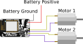
Motors are attached to M1 and M2 of the RoboPad in a simple 2-wheel Tank-Drive Robot.

IO Configuration
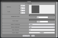
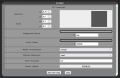
In order to tell the RoboPad that there are two motors attached, you will need to configure the IO Units on the device. The RoboPad has special IO Units available for drive motors called "Built-in H-Bridge Motor" units. These use the internal H-bridges to drive the motors forwards and backwards:

They allow you tot set a "Forward Scale" and a "Reverse Scale" for each, which lets you change how fast the attached motors spin when told to go all the way forward or backward, which is useful for tuning a robot if it's not driving straight when you tell it to go forward or backward, or just to slow it down if forward or backwards is too fast. They should be there by default, and if not you can add them with the "Add" menu at the top of the IO Configuration page.
Nodegraph Configuration
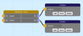
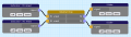
By adding the H-Bridge Motor IO Units, the Chip Node in the Nodegraph Editor gains 2 new inputs and 2 new outputs:

The two input ports - here named "M1" and "M2" (because that's the name of each motor in the IO Configuration) - drive each motor. They expect values between 0 and 1, with 0 being "full reverse" and 1 being "full forward". The two outputs - here named "M1 armed" and "M2 armed" - indicate whether the motors are armed. The concept of actuator arming can feel a little complex, but it is important because without it the chance of accidentally driving a motor is much higher: any actuator is considered "armed" once the actuator has recieved a drive signal corresponding to it's "safe state". In the case of H-Bridge IO Units, the "safe state" is not moving, meaning that the RoboPad must recieve a value of 0.5 on each of the M1 and M2 input ports before each motor will move in any other way. Without this, it would be possible to (for example) add a signal to the M1 port that constantly fed the port with a value of "1", which would cause the robot to start driving it's M1 wheel immediately as soon as the controller was accessed, which wouldn't be safe:

Fortunately for us, the Slider Node defaults to emitting the value 0.5, so we can simply connect two Sliders to the M1 and M2 inputs. In the images below, we've hooked them up and positioned them on the Controller Stage so that one is on the left and one on the right (use the left and right buttons to see additional images):
Two Sliders attached to the RoboPad chip node.
The left slider configuration - it's positioned on the left of the screen, with a default value of 0.5 and "reset" behaviour. This means that as the stick is dragged up and down it will emit values between 0 and 1, driving M1 backwards and forwards, and when released it will output 0.5, stopping the motor.
The right slider configuration - it's positioned on the right of the screen, with a default value of 0.5 and "reset" behaviour. This means that as the stick is dragged up and down it will emit values between 0 and 1, driving M2 backwards and forwards, and when released it will output 0.5, stopping the motor.


However, while this is the minimum requirements to drive a robot using two sliders, it is often helpful to keep track whether your actuators are armed, which is why by default the RoboPad is bundled with a more advanced nodegraph that includes two Indicator Nodes that change from dark to light green when each actuator is activated (again, use the arrows to see additional images):
In this nodegraph, two Indicators have been added to indicate the armed status of the two drive motors.
The left (M1) indicator has been placed above the left slider. The label visibility has been turned off and it set to "binary" mode so that it only turns a lighter shade of green to indicate the motor is armed.
The right (M2) indicator has been placed above the right slider. The label visibility has been turned off and it set to "binary" mode so that it only turns a lighter shade of green to indicate the motor is armed.


The nodegraph for this example is actually the default configuration of the RoboPad, so resetting the nodegraph and IO Configs via the Management Page should set it to this. However, you can download the nodegraph for yourself here. The IO Configuration can be found here.