Example: Simple Joystick-Drive Robot: Difference between revisions
(Clones from Tank-drive) |
(→Troubleshooting: Adds troubleshooting guidelines) |
||
| (8 intermediate revisions by the same user not shown) | |||
| Line 1: | Line 1: | ||
'''''<u>NOTICE: This page consists of information on a feature currently in [[Beta]]. Information is liable to change or be incomplete.</u>''''' | '''''<u>NOTICE: This page consists of information (the IO Config editor) on a feature currently in [[Beta]]. Information is liable to change or be incomplete. However, a similar nodegraph is constructable for version 2.3 or lower builds of RoboPad.</u>''''' | ||
While a [[Example: Simple Tank-Drive Robot|tank-drive robot]] is the most simple type of robot that you can make with a RoboPad, many people want to control both drive motors of a simple two-motor robot with a single [[Joystick Node|Joystick]]. This page aims to give you a walk-through of building a robot that can be driven in this manner. | |||
The nodegraph from this example can be found [https://yelllowcube.sharepoint.com/:u:/s/BlayzeTechLimited/ | The nodegraph from this example can be found [https://yelllowcube.sharepoint.com/:u:/s/BlayzeTechLimited/EctL76vbaS5HupqStJggtA8BuB2ThmnzbZDuQlYE2ZUg0g?e=57FshM here] (click the download button in the top left of the viewer to get a local copy that can be uploaded via the [[The Management Page#Node Graph Management|Nodegraph Management Page]]). | ||
The IO Configuration can be found [https://yelllowcube.sharepoint.com/:u:/s/BlayzeTechLimited/EdDMS4fiFFNBk0XiUJGwuLEB8vUZF1rG9RE07kyvFVDZIw?e= | The IO Configuration can be found [https://yelllowcube.sharepoint.com/:u:/s/BlayzeTechLimited/EdDMS4fiFFNBk0XiUJGwuLEB8vUZF1rG9RE07kyvFVDZIw?e=3PVTYd here]. | ||
== Hardware == | == Hardware == | ||
| Line 22: | Line 22: | ||
By adding the H-Bridge Motor IO Units, the [[Chip Node]] in the [[Nodegraph Editor]] gains 2 new inputs and 2 new outputs: | By adding the H-Bridge Motor IO Units, the [[Chip Node]] in the [[Nodegraph Editor]] gains 2 new inputs and 2 new outputs: | ||
[[File:Chip Node with Default IO.png|center|thumb|437x437px|The Chip Node gets a pair of "<motor name> armed" output and "<motor name>" inputs, allowing you to drive the motors and get their status.]] | [[File:Chip Node with Default IO.png|center|thumb|437x437px|The Chip Node gets a pair of "<motor name> armed" output and "<motor name>" inputs, allowing you to drive the motors and get their status.]] | ||
The two input ports - here named "M1" and "M2" (because that's the name of each motor in the IO Configuration) - drive each motor. They expect values between 0 and 1, with 0 being "full reverse" and 1 being "full forward". The two outputs - here named "M1 armed" and "M2 armed" - indicate whether the motors are [[IO Config Editor#Actuators|armed]]. The concept of actuator arming can feel a little complex, but it is important because without it the chance of accidentally driving a motor is much higher: any actuator is considered "armed" once the actuator has recieved a drive signal corresponding to it's "safe state" | The two input ports - here named "M1" and "M2" (because that's the name of each motor in the IO Configuration) - drive each motor. They expect values between 0 and 1, with 0 being "full reverse" and 1 being "full forward". The two outputs - here named "M1 armed" and "M2 armed" - indicate whether the motors are [[IO Config Editor#Actuators|armed]]. The concept of actuator arming can feel a little complex, but it is important because without it the chance of accidentally driving a motor is much higher: any actuator is considered "armed" once the actuator has recieved a drive signal corresponding to it's "safe state" (see the [[Example: Simple Tank-Drive Robot|Tank Drive example]] for more information on this - in this example, we assume knowledge of arming mechanics, and include armed status indicators). | ||
[[File: | |||
In order to drive the motors M1 and M2, we will employ the use of a [[Joystick Node]] and a [[Joystick Mixer Node]]. By default the Joystick Node outputs two values: The position of the "stick" within the joystick in terms of it's X and Y position, between 0 and 1. We could hook this directly up to the M1 and M2 inputs if we wanted to: | |||
File:Basic | [[File:Bad-joystick-config.PNG|center|thumb|A badly-connected joystick nodegraph that will cause incorrect motor drive.]] | ||
File: | However, this would result in moving the joystick left and right driving one wheel (if M1 is connected to it as in this example, the left wheel) only of the robot, and moving it vertically drives the other (here, the right): | ||
[[File:Bad-joystick-config-diagram.PNG|center|thumb|A very difficult to drive robot.]] | |||
In this case, driving the robot is very difficult. In the example above, moving the stick to the top right results in the robot moving forward, and the top left has it just spinning counter-clockwise in-place. We need some kind of mixing so that moving the stick up makes the robot move forwards, down backwards and left and right makes it turn left and right variably. Fortunately, that's what the [[Joystick Mixer Node]] is for: | |||
[[File:Basic-joystick-drive-nodegraph.png|center|thumb|A properly mixed joystick node.]] | |||
Now the robot should drive something more like this: | |||
File: | [[File:Good-joystick-diagram.png|center|thumb|When a joystick mixer node is used, the robot will drive forward when the joystick is moved upwards, and turn left and right as the joystick is moved left and right.]] | ||
While this is still a relatively simple control scheme, it can still be a little confusing, especially if you decide to make any changes to the output of the Joystick Node before they go into the mixer node. In this case [[Indicator Node|Indicator Nodes]] can be very useful as they can be configured to display a value directly which can help you debug your nodegraph. In the final version of this example configuration, we use two to indicate whether the motors have been armed: | |||
[[File:Joystick-drive-with-indicators.PNG|center|thumb|Here we have connected two indicators to tell us if and when the drive motors are armed.]] | |||
The nodegraph for this example can be downloaded [https://yelllowcube.sharepoint.com/:u:/s/BlayzeTechLimited/EctL76vbaS5HupqStJggtA8BuB2ThmnzbZDuQlYE2ZUg0g?e=57FshM here]. The IO Configuration can be found [https://yelllowcube.sharepoint.com/:u:/s/BlayzeTechLimited/EdDMS4fiFFNBk0XiUJGwuLEB8vUZF1rG9RE07kyvFVDZIw?e=jLDhIO here]. | |||
Using a joystick node opens up a lot of real estate on your screen and (since it's a single-finger input), gives you the chance to add additional controlls on the screen. It's the perfect input mode to use alongside a [[Slider Node]] to drive a [[IO Config Editor#Servo Motor|Servo]] as a lifter for your robot. | |||
== Troubleshooting == | |||
Even though you've configured your nodegraph following this page, you might still have some issues with driving your robot - these can arise when the physical configuration of the robot doesn't match up with the software settings you've configured - usually this can be that your left and right motors are flipped, or the power to one of the motors is inverted. You can of course fix these by re-soldering, but you can also usually just change the nodegraph as appropriate. Below are some common situations and their solutions. | |||
=== The Robot Drives Backwards When the Stick is Pushed Forwards === | |||
In this case, it's likely that the drive motors have been soldered in the opposite polarity to the nodegraph configuration - you could reverse the polarity of the motors, or you can invert the output of the [[Joystick Node|joystick UI node]]. In the node's settings, there is an option for '''invert Y axis''' which will mean that instead of the y-axis output port emitting 0 when the joystick is at the bottom and 1 when it is at the top, it will emit 1 when at the bottom and 0 when at the top, flipping the forward/backward behaviour. | |||
Note that you could also achieve this behaviour by putting an [[Inverter Node]] between the ''y'' output port of the Joystick and the ''yaxis'' input of the [[Joystick Mixer Node]]. | |||
=== The Robot Turns The Wrong Way === | |||
If the robot is turning right when you want to turn left (and vice-versa), this is similar to the previous issue, and can be solved in a similar way - you must '''invert the X axis''' before the signal gets to the [[Joystick Mixer Node]]. You can also achieve this same result by disconnecting the Joystick Mixer's ''left/right drive'' output ports and the [[Chip Node]]'s ''M1'' and ''M2'' ports and then connecting them in the other order, so that the drive signals cross and each of the Joystick Mixer Node's ''drive'' outputs is driving the opposite side it was before. The physical solution to this issue is usually switching which motor is connected to which "M" port - i.e. if M1 was left and M2 right, switch M2 to left and M1 to right. | |||
=== Instead of Driving Forward, the Robot Turns === | |||
Lift the robot up off of its wheels - when you push the stick up to drive forward, do the wheels turn in opposite directions? When you pull the stick back to attempt to drive backwards, do they spin again in opposite directions but the other way? In this situation only '''one''' motor is connected in it's inverted polarisation. You could fix this by flipping the polarisation of the motor that is moving in the way you don't want it to, or you could connect an [[Inverter Node]] between the [[Joystick Mixer Node]]'s output ''left/right drive'' port and the Chip's ''M1'' or ''M2'' port (depending on which motor you want to invert). | |||
=== The Robot Turns or Moves Too Fast === | |||
Controlling a robot from a phone can be finickety at times, and if your robot's got fast motors, you can loose control when turning. A simple way of reducing turning speed is to add a [[Scaler Node]] between the ''x'' output of the [[Joystick Node|Joystick]] and the ''xaxis'' input of the [[Joystick Mixer Node|Joystick Mixer]]. At this point the '''scale size''' can be set to some value lower than 1 to ''scale'' down the input signal so instead of emitting between 0 and 1, it might emit between, say, 0.3 and 0.8. | |||
Scaler nodes can also be added to the Joystick's ''y'' output port to scale down speed. Or, if you prefer to keep the nodegraph simple, you can manually set the forward and backward scales in the [[IO Config Editor#Built-in H-Bridge Motor|H-Bridge IO Config settings]]. | |||
Latest revision as of 16:27, 21 August 2024
NOTICE: This page consists of information (the IO Config editor) on a feature currently in Beta. Information is liable to change or be incomplete. However, a similar nodegraph is constructable for version 2.3 or lower builds of RoboPad.
While a tank-drive robot is the most simple type of robot that you can make with a RoboPad, many people want to control both drive motors of a simple two-motor robot with a single Joystick. This page aims to give you a walk-through of building a robot that can be driven in this manner.
The nodegraph from this example can be found here (click the download button in the top left of the viewer to get a local copy that can be uploaded via the Nodegraph Management Page).
The IO Configuration can be found here.
Hardware
Tank drive robots have only two actuators: A left drive motor and a right drive motor, both attached to a wheel. After attaching your power supply to the "+" and "-" pins, it simply requires that two motors be soldered - one each to the M1 and M2 pin pairs on the RoboPad.
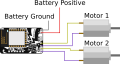
Motors are attached to M1 and M2 of the RoboPad in a simple 2-wheel Tank-Drive Robot.

IO Configuration
In order to tell the RoboPad that there are two motors attached, you will need to configure the IO Units on the device. The RoboPad has special IO Units available for drive motors called "Built-in H-Bridge Motor" units. These use the internal H-bridges to drive the motors forwards and backwards:

They allow you tot set a "Forward Scale" and a "Reverse Scale" for each, which lets you change how fast the attached motors spin when told to go all the way forward or backward, which is useful for tuning a robot if it's not driving straight when you tell it to go forward or backward, or just to slow it down if forward or backwards is too fast. They should be there by default, and if not you can add them with the "Add" menu at the top of the IO Configuration page.
Nodegraph Configuration
By adding the H-Bridge Motor IO Units, the Chip Node in the Nodegraph Editor gains 2 new inputs and 2 new outputs:

The two input ports - here named "M1" and "M2" (because that's the name of each motor in the IO Configuration) - drive each motor. They expect values between 0 and 1, with 0 being "full reverse" and 1 being "full forward". The two outputs - here named "M1 armed" and "M2 armed" - indicate whether the motors are armed. The concept of actuator arming can feel a little complex, but it is important because without it the chance of accidentally driving a motor is much higher: any actuator is considered "armed" once the actuator has recieved a drive signal corresponding to it's "safe state" (see the Tank Drive example for more information on this - in this example, we assume knowledge of arming mechanics, and include armed status indicators).
In order to drive the motors M1 and M2, we will employ the use of a Joystick Node and a Joystick Mixer Node. By default the Joystick Node outputs two values: The position of the "stick" within the joystick in terms of it's X and Y position, between 0 and 1. We could hook this directly up to the M1 and M2 inputs if we wanted to:

However, this would result in moving the joystick left and right driving one wheel (if M1 is connected to it as in this example, the left wheel) only of the robot, and moving it vertically drives the other (here, the right):

In this case, driving the robot is very difficult. In the example above, moving the stick to the top right results in the robot moving forward, and the top left has it just spinning counter-clockwise in-place. We need some kind of mixing so that moving the stick up makes the robot move forwards, down backwards and left and right makes it turn left and right variably. Fortunately, that's what the Joystick Mixer Node is for:

Now the robot should drive something more like this:

While this is still a relatively simple control scheme, it can still be a little confusing, especially if you decide to make any changes to the output of the Joystick Node before they go into the mixer node. In this case Indicator Nodes can be very useful as they can be configured to display a value directly which can help you debug your nodegraph. In the final version of this example configuration, we use two to indicate whether the motors have been armed:

The nodegraph for this example can be downloaded here. The IO Configuration can be found here.
Using a joystick node opens up a lot of real estate on your screen and (since it's a single-finger input), gives you the chance to add additional controlls on the screen. It's the perfect input mode to use alongside a Slider Node to drive a Servo as a lifter for your robot.
Troubleshooting
Even though you've configured your nodegraph following this page, you might still have some issues with driving your robot - these can arise when the physical configuration of the robot doesn't match up with the software settings you've configured - usually this can be that your left and right motors are flipped, or the power to one of the motors is inverted. You can of course fix these by re-soldering, but you can also usually just change the nodegraph as appropriate. Below are some common situations and their solutions.
The Robot Drives Backwards When the Stick is Pushed Forwards
In this case, it's likely that the drive motors have been soldered in the opposite polarity to the nodegraph configuration - you could reverse the polarity of the motors, or you can invert the output of the joystick UI node. In the node's settings, there is an option for invert Y axis which will mean that instead of the y-axis output port emitting 0 when the joystick is at the bottom and 1 when it is at the top, it will emit 1 when at the bottom and 0 when at the top, flipping the forward/backward behaviour.
Note that you could also achieve this behaviour by putting an Inverter Node between the y output port of the Joystick and the yaxis input of the Joystick Mixer Node.
The Robot Turns The Wrong Way
If the robot is turning right when you want to turn left (and vice-versa), this is similar to the previous issue, and can be solved in a similar way - you must invert the X axis before the signal gets to the Joystick Mixer Node. You can also achieve this same result by disconnecting the Joystick Mixer's left/right drive output ports and the Chip Node's M1 and M2 ports and then connecting them in the other order, so that the drive signals cross and each of the Joystick Mixer Node's drive outputs is driving the opposite side it was before. The physical solution to this issue is usually switching which motor is connected to which "M" port - i.e. if M1 was left and M2 right, switch M2 to left and M1 to right.
Instead of Driving Forward, the Robot Turns
Lift the robot up off of its wheels - when you push the stick up to drive forward, do the wheels turn in opposite directions? When you pull the stick back to attempt to drive backwards, do they spin again in opposite directions but the other way? In this situation only one motor is connected in it's inverted polarisation. You could fix this by flipping the polarisation of the motor that is moving in the way you don't want it to, or you could connect an Inverter Node between the Joystick Mixer Node's output left/right drive port and the Chip's M1 or M2 port (depending on which motor you want to invert).
The Robot Turns or Moves Too Fast
Controlling a robot from a phone can be finickety at times, and if your robot's got fast motors, you can loose control when turning. A simple way of reducing turning speed is to add a Scaler Node between the x output of the Joystick and the xaxis input of the Joystick Mixer. At this point the scale size can be set to some value lower than 1 to scale down the input signal so instead of emitting between 0 and 1, it might emit between, say, 0.3 and 0.8.
Scaler nodes can also be added to the Joystick's y output port to scale down speed. Or, if you prefer to keep the nodegraph simple, you can manually set the forward and backward scales in the H-Bridge IO Config settings.